By Brian Walker, Senior Scientist, RF Applications
Introduction
Calibration is the foundation of accurate vector network analyzer measurement.1 Raw VNA data include systematic errors from the instrument, test cables, connectors, adapters, and transitions. Calibration characterizes these errors and mathematically removes their effects so the displayed S-parameters more closely represent the device under test.
No single calibration method is ideal for every application. The appropriate choice depends on the measurement, required accuracy, frequency range, DUT interface, calibration time, and practical test environment. The objective is to use the simplest calibration that provides the required accuracy.
Understanding What Calibration Corrects
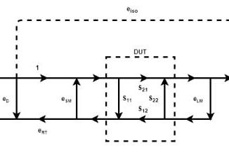
The principal systematic errors are directivity, source match, load match, reflection tracking, transmission tracking, and isolation.2 Directivity limits the ability to distinguish a small DUT reflection from leakage within the measurement system. Source and load match errors result from impedance mismatch at the VNA ports and test cables, producing multiple reflections and frequency-dependent ripple. Reflection and transmission tracking correct frequency-dependent amplitude and phase response in the respective measurement paths. Isolation corrects leakage between source and receiver paths, which can become important when measuring very high attenuation or isolation.
Different calibration methods solve for different subsets of these errors. More comprehensive calibration generally improves accuracy, but requires additional standards, connections, or calibration time.
Choosing a Calibration Method
Begin with the measurement requirement. If only reflection or impedance is needed, a one-port calibration may be sufficient. Measurements of insertion loss, gain, isolation, or phase require characterization of the transmission path. Connectorized coaxial devices are usually well suited to SOLT or ACM calibration, while fixtures, printed circuit boards, and on-wafer measurements often favor TRL.
Frequency range and accuracy also matter. TRL can provide exceptional accuracy in a fixture, but a single Line generally covers only about three octaves and becomes impractical at low frequencies because of the required physical line length. In production, calibration speed and repeatability may be as important as minimum residual error. Regardless of method, moving cables, adding adapters, changing connectors, or large temperature changes after calibration can increase uncertainty.
Response and Enhanced Response Calibration
Response calibration is the simplest and fastest approach. A transmission Response calibration normally uses a Thru to correct transmission tracking, removing the frequency-dependent loss and phase response of the measurement system. It does not correct directivity, source match, load match, or isolation, so it is most appropriate when transmission response is the primary concern and moderate uncertainty is acceptable.
Enhanced Response calibration adds selected standards to correct additional error terms without performing a complete calibration. For reflection measurements, adding a Load can correct directivity, while an Open and Short can provide source-match information. This approach is useful when one particular error term dominates the uncertainty and a full calibration is unnecessary.
SOL One-Port Calibration
SOL calibration uses Short, Open, and Load standards to solve for the complete one-port error model: directivity, source match, and reflection tracking. It establishes the reference plane where the standards are connected and provides accurate return loss, reflection coefficient, VSWR, and impedance measurements. SOL is appropriate when accurate reflection measurement is required but transmission through the DUT is not.
Two-Port One-Path Calibration
Two-Port One-Path calibration is useful when a protective attenuator must remain on the receiving port, as in high-power amplifier measurements. A full SOL calibration is performed on Port 1, followed by a Thru measurement through the attenuated Port 2 path. The method corrects directivity, source match, reflection tracking, transmission tracking, and isolation, but not Port 2 load match.3 With a high-quality fixed attenuator, the remaining load-match error is generally small, while the attenuator protects the VNA receiver.
SOLT Calibration
SOLT extends SOL calibration to both ports and adds a precision Thru, allowing the VNA to solve for the complete two-port error model. It provides accurate measurement of all four S-parameters and is the general-purpose standard for connectorized coaxial measurements.
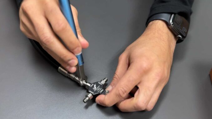
Its accuracy depends on correct calibration-kit definitions, good connector condition, proper torque, and stable test cables. Mechanical Open, Short, and Load standards are not ideal devices, so errors in their models contribute directly to residual uncertainty. Test cables should remain in their relaxed position after calibration because flexure can alter phase and match.
| Cal Type | Directivity | Source Match | Load Match | Reflection Tracking | Transmission Tracking | Isolation |
| Open or Short | X | X | X | Partial | X | X |
| Thru | X | X | X | X | Partial | X |
| Open-Load or Short-Load | ✔ | X | X | Partial | X | X |
| Open-Short | X | ✔ | X | Partial | X | X |
| SOLT | ✔ | ✔ | ✔ | ✔ | ✔ | ✔ |
Using an Automatic Calibration Module (ACM)
An Automatic Calibration Module uses internally switched, data-based standards whose actual electrical responses are characterized during manufacturing. Unlike a conventional mechanical kit that generally treats the Load as an ideal 50-ohm termination, ACM uses the measured complex reflection coefficient of its internal Load and applies thermal correction.4
This can substantially improve residual directivity in demanding reflection measurements. The ACM also provides a Confidence Check using an internally characterized attenuator, allowing the completed calibration to be verified without disturbing the setup. Electronic switching reduces connector wear, improves operator-to-operator repeatability, and makes calibration very fast, which is particularly valuable in production and automated systems.
TRL Calibration
TRL, or Thru-Reflect-Line, derives the VNA error terms from transmission-line standards rather than precision Open, Short, and Load standards.5 The Thru establishes the reference planes, the Reflect provides a high reflection, and the Line provides additional electrical length. The exact Reflect coefficient need not be known, provided its magnitude is high and it is similar at both ports.
TRL is especially effective for PCB fixtures, planar structures, wafer probing, and other environments where standards can be fabricated using the same transmission-line technology as the DUT. It can establish the reference plane within the structure and avoids the residual-directivity limitation imposed by a nonideal Load.
The Line must provide suitable phase separation from the Thru, generally about 20 to 160 degrees.6 Multiline TRL uses several Line lengths to extend useful bandwidth. TRL can provide exceptional accuracy, but its performance depends on accurately fabricated transmission lines, stable connections, and controlled environmental conditions.
Conclusion
Calibration should be selected according to the measurement rather than by automatically choosing the most elaborate method available. Response calibration is efficient for straightforward transmission measurements. SOL provides complete one-port reflection correction, while SOLT remains a versatile choice for general coaxial two-port measurements. Two-Port One-Path calibration is valuable when a protective attenuator must remain in the measurement path. ACM combines comprehensive correction with fast automated operation, characterized standards, reduced connector wear, and built-in verification. TRL is particularly powerful for fixtures, planar structures, and on-wafer measurements.
Whatever method is used, calibration cannot compensate for poor measurement practice. Clean connectors, stable test cables, careful handling, thermal stability, and verification remain essential to obtaining trustworthy VNA measurements.
Footnotes
- B. Walker, Introduction to the Metrology of VNA Measurement. Copper Mountain Technologies, 2022. ↩︎
- D. Rytting, Network Analyzer Error Models and Calibration Methods, Hewlett-Packard/Agilent Technologies. ↩︎
- Copper Mountain Technologies, VNA Operating and Programming Manual. ↩︎
- Copper Mountain Technologies, Automatic Calibration Module (ACM) User Guide. ↩︎
- G. F. Engen and C. A. Hoer, “Thru-Reflect-Line: An Improved Technique for Calibrating the Dual Six-Port Automatic Network Analyzer,” IEEE Transactions on Microwave Theory and Techniques, vol. MTT-27, no. 12, pp. 987-993, Dec. 1979. ↩︎
- J.P. Dunsmore, Handbook of Microwave Component Measurements: With Advanced VNA Techniques, 2nd ed., Wiley, 2020. ↩︎