Introduction
Electrical safety testers – often referred to as “hipot” testers – are an integral part of electrical and electronic equipment manufacturing. Hipot testers get their name from the high-potential (high voltage) they produce to perform dielectric withstand and insulation resistance tests. In addition to these tests, many hipot testers provide accurate low-resistance measurements and low-resistance/high-current outputs to test ground resistance and ground bond integrity.
Hipot testing has long been a standard procedure for assuring the electrical safety of electronic equipment. Early commercial hipot testers were actually not much more than a step-up transformer to adjust to applied voltage in stepped increases over prescribed time segments to test for leakage or component breakdown. This method could easily lead to incorrect results when leakage current caused the voltage output from a high impedance transformer source to droop. Modern hipot testers utilize electronic source technology to assure compliance with IEC-61010 that explicitly requires that “the voltage test equipment shall be able to maintain the required voltage for the specified period of time.”
Product Safety Certification
Electrical safety testing and certification is a requirement for virtually every electronic device and electrical apparatus. The details of what constitutes a certified product is dependent upon a daunting number (hundreds) of safety standards and the region of the world where the device will be sold and used. Standards setting organizations include:
- EN / IEC (European)
- UL (US)
- CSA (Canada)
- CCC (China)
- JEIDA / MITI (Japan)
Manufacturers must submit samples of their products to recognized certification agencies. Nationally Recognized Certification Laboratories (NRTLs) include UL, VDE, FM, ETL and others. The agency certification process is conducted to confirm compliance with the relevant standard(s). This compliance evaluation investigates two key areas:
- Construction – Mechanical construction, spacing, clearances, etc.
- Safety – To assure safe operation (even under high-stress conditions)
Work is being done to harmonize standards from global agencies. For example:
- The IEC 61800-5-1 is a safety standard specified by the International Electrotechnical Commission for adjustable-speed electrical power drive systems. It covers the safety aspects related to electrical, thermal and energy. The former UL standard (UL508C) has now been supplanted by new standard, harmonized with the IEC requirements.
- The UL document announcing this change put it
this way:
- “This harmonization work was undertaken with the intent of creating a standard that, while being based upon and adopting IEC requirements, would incorporate national differences that would address U.S. installation requirements (NFPA 70, US National Electrical Code). This goal has largely been accomplished in all cases.”
To further help manufactures address this often-bewildering array of international (and sometimes conflicting) standards, the Power Sources Manufacturers Association (PSMA) has established a standing committee and forum on its website.
Production Electric Safety Testing
Electrical safety testing is an important final step in the production process for most electrical and electronic equipment to:
- Assure compliance safety agency labeling requirements
- Detect defective components or assembly flaws
- Reduce incidence of latent field failures and the attendant warranty costs
Once in production, products must be 100% tested to confirm compliance with the related agency certifications and safety standards. Production tests are less stringent than initial certification but will generally include basic dielectric withstand and shock hazard (leakage) tests. Plug-connected devices will also be subjected to ground resistance and (if the standard requires) ground bond tests. Electrical motors, transformers and other such devices will likely include insulation resistance tests.
Periodic inspection and
calibration of test equipment is a standard requirement to maintain NRTL
certification. Agency inspection will include check of hipot instrument
calibration certification. This “cal cert” is typically required on an annual
basis. (UL and other NRTLs require compliance certification with ISO17025.) Another common requirement prescribed by most
NRTLs is a daily functional test of the hipot equipment.
Dielectric Withstand – Hipot
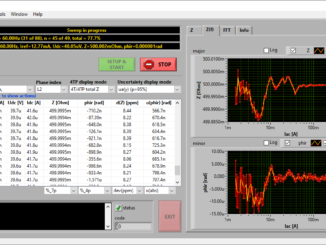
The basic hipot test applies a high voltage from the conductors to the chassis of the device-under-test (DUT). This test is often referred to as “dielectric” or “voltage” withstand. Its purpose is to confirm that the insulation and isolation of the non-conducting surfaces from the operating voltage is sufficient to avoid a shock hazard. The typical specification for this test is: 1000V + 2 x normal operating voltage. Refer to Figure 1, above.
Both AC and DC hipot tests are possible and, in general, the test should use the same type of voltage as it would be during normal operation. However, if a DC hipot test is used on an AC circuit, the hipot voltage should be two times the peak (2 x 1.4 x RMS)+ 1000V.
Depending on the applicable standard, units pass this test if either:
- the leakage current measured is less than the maximum allowable current;
- no breakdown occurs, i.e., no sudden and uncontrolled flow of current.
For double-insulated products, higher voltages will often be specified in the test standard. In addition, this class of device typically requires special fixturing to connect the non-conductive outer shell to a conductive element.
Defects that are often detected with the hipot test include contamination (dirt, debris) and lack of proper spacing (creepage and clearance) of components. Creepage is measured across surfaces, clearance is the air gap between components. Contamination would likely cause an unacceptable level of leakage current. Clearance problems could result in breakdown.
Desirable Dielectric Withstand Test Features
- Adjustable maximum
output voltage:
- 5KV is adequate for many applications
- Higher voltages (up to 30KV) may be required
- AC and DC outputs
- Excellent regulation – both line and load
- Controllable ramp rates, dwell times and discharge features
- Phase angle measurement of leakage current – capacitive coupling detection
- Some standards allow for in-phase and quadrature current to be measured separately. Leakage current due to capacitive coupling may not be a safety concern
- Min / max pass /
fail current limits
- Separate limits during ramp
- Programmable multichannel testing
Insulation Resistance
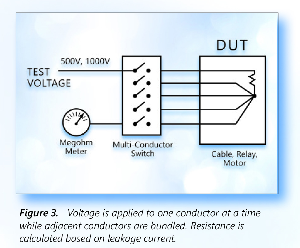
Insulation resistance testing is likely to be required in motor winding, transformer winding and other applications involving cabling or insulated wire. Insulation resistance testing typically involves confirming that the resistance exceeds a defined high resistance value.
In many instances, insulation resistance needs to be measured between several conductors. Examples include cable/connector assemblies, multiconductor cables and relays. To make this measurement, all the conductors except one are shorted together and the test voltage is applied from the remaining conductor across the bundled ones. Each wire is then, in turn, tested in this fashion (Figure 3).
Desirable Insulation Resistance Test Features
- Wide range of selectable test voltages
- Accurate/repeatable high-resistance measurement
- Programmable high-voltage switching accessory
- Multichannel programmable testing
- Pass on steady and Increasing voltage

Ground Continuity
Ground continuity testing is performed to confirm that the conductive chassis of a device is safely connected to the earth ground pin on the power plug. This assures protection against shock hazards even if the equipment suffers an internal short to the chassis. The current would be shunted via the ground wire and would likely trip the breaker or blow the fuse.
Ground continuity is performed by measuring by applying a low current (e.g., 50 mA) and calculating the resistance from the ground pin on the power plug to selected locations on the exposed surfaces of the DUT. Desirable ground continuity features include:
- Accurate, repeatable low resistance meter
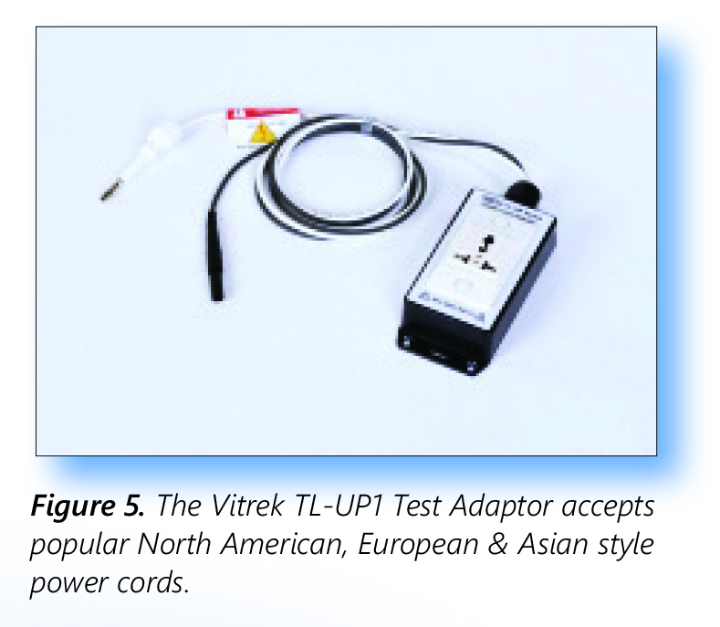
- Plug adaptor accessory to speed testing
Vitrek’s TL-UP1 accessory (Figure 5) is an example of an accessory device the simplifies ground continuity test setup. With its 4-foot leads, the accessory offers easy hipot and continuity test connection of corded products.
Ground Bond
Where ground continuity measures the resistance of the safety ground connection, the ground bond test assures the integrity of the connection. Using the same test setup, a high current is passed through the circuit. If the ground bond is solid, the current passes without a change in resistance. If weak, the resistive heating of the current would induce a failure of the bond.
Desirable Ground Bond Test Features
- Accurate high current source
- Programmable test currents and test times
- Plug adaptor accessory to speed testing
- 4-wire milliohm meter – providing a Kelvin connection for highly accurate low resistance measurements.

Written by Kevin Clark, CEO, Vitrek Inc.