by Dan Wiswell
We’ve all heard people speak of accuracies and tolerances in more colorful language than what would be expected in a metrology lab. “Plus-or-minus a hand grenade” or, “Close enough for government work” are a few. Some gentlemen that I have worked with in the past often used anatomical references to describe the electrical or mechanical specifications of a device or process, but that only goes so far. When you just eyeball something (whether your observation is accurate or not) by considering what you behold, you exert an influence on its relationship with the universe. As we have created ever more accurate instruments, we have done so to push past the technological status quo because of a particular need, and then refine them as the state-of-the-art progresses. When electrical instruments were first created, people working with them in the late nineteenth and early twentieth centuries rarely expected high-precision measurements like those that we are used to making now. Laboratory-grade instruments that measured DC voltages at tolerances better than +/-.25% of reading were ahead of the curve back then. The influence of those measuring devices on the parameter that was being observed could be dramatically different depending on the observer, and/or the instrument being used.
As a student learning about electricity, I saw an old military documentary about the proper use of a Volt, Ohm, Amp Meter. Back then they were called VOMs. The instructor said that one of the specifications of the VOM he was speaking about was “twenty-thousand ohms-per-volt on DC Voltage ranges.” I remember not understanding why this was important, but I tucked that thought away until the day I could make some sense of it.
In the first calibration lab I worked in, we had a set of standard cells like those pictured below.
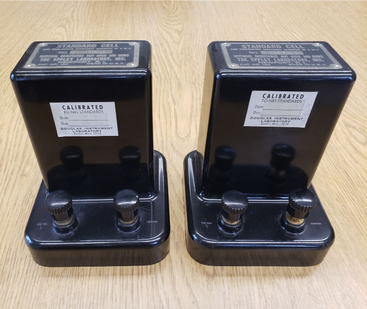
We used them as our voltage standards for the laboratory. They both provided a voltage source of 1.018xx volts DC that was measured by a very high-impedance voltmeter. We had two so that one could be sent out for calibration while we used the other in its absence. Once, an older gentleman in the lab had me observe the high-impedance voltmeter as he used a VOM to measure the standard cell at the same time. The moment his test probes made contact, the readings that I was observing began to steadily decrease, and then recover as he removed his probes. He asked me if I understood what had just happened, and then explained how the VOM had loaded down the standard cell by drawing the current required to get the indication it produced. In those days, the most accurate and sophisticated voltmeters in our lab were VTVMs, or Vacuum Tube Volt Meters. These instruments had very high input impedances and when they were connected to our standard cells, they barely disturbed their quiescent voltages. Which brings us back to the days of old. Look at this Weston Model 540 DC Volt-Ammeter built in 1895.
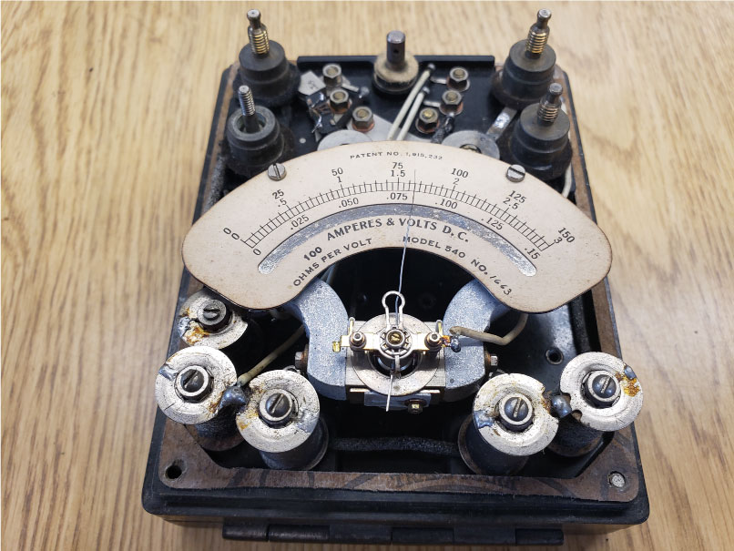
At 100 ohms per volt, this meter would have loaded a circuit down two hundred times more than the VOM my instructor was demonstrating. Ohm’s law would say that if it’s indicating one volt, it must be drawing ten milliamps. That’s not only enough to create a spark, but it would also be quite a burden as compared to the typical digital handheld voltmeters of today that have ten megohm input impedances. Meters currently used for the same measurement would shunt off ten nano amps during the same test. It’s no wonder why the laboratory sets depicted in old Frankenstein movies were arcing and sparking, that was probably caused by the kilovoltmeter connections to the circuit!
It takes careful consideration when designing instruments that are not only sensitive but are also innocuous to the circuit being tested. Of the three Ohm’s law parameters, current measurement was the earliest and most studied electrical property. Beginning with direct current measurement, instruments were designed with meter movements and shunts that could provide accurate readings from microamps to many thousands of amperes. Direct-current meters are connected in series directly into the path of current flow and so can be construed as being part of the original, pristine circuit path. A voltmeter, when connected to the circuit, creates a path of its own that parallels the “primary” circuit. This creates a circuit with its own budgets, the properties of which may become too outsized to manage directly. High-voltage measurements are an example of this condition. Stresses not present in lower voltage situations can make direct, physical-contact measurement dangerous or impractical in high voltage circuits. The effects of corona and partial discharge can cause leakage currents to flow in the circuit creating carbon paths and other degradations of the circuit. In these scenarios, electrostatic measurements offer an elegant solution.
The instrument pictured below is a Model ESH made by the Sensitive Research Company. It is a three-range, thirty-thousand-volt electro-static voltmeter.


Its ranges are selected by changing the orientation of a movable electrode that protrudes from the turret at the back of the instrument. On the lowest range the adjustable electrode is positioned at its closest proximity to a moving vane on the meter movement. The higher the measured voltage, the farther the high-voltage electrode is spaced in relation to the movement. Apart from the adjustable electrode, the entire rest of the circuit is connected to ground. This style of electro-static voltmeter made by the Sensitive Research Company was very expensive to manufacture as they were machined from a single block of aluminum. This created an instrument with very small “islands of potential” in its overall design. The top cover of the instrument was gasketed to minimize the ingress of foreign material.
The measured input impedance of a perfect electro-static meter movement should be infinite, if that was possible. These meter movements are deflected by static attraction or repulsion. This effect will yield non-linear readings across its arc of measurement. This is due to the relatively weak field-strength of the applied electrical signal at lower voltages. To compensate for this, manufacturers would hand-point each individual meter’s scale to achieve the best degree of accuracy for a given meter movement. At higher voltages, the elevated field strength becomes an advantage in the application of this technology. Electro-static meter movements have an added advantage of also being able to measure high-voltage AC test signals as well and do so over a broad range of low frequencies and crest factors. When using these high-voltage instruments, it is very important to allow them to electrically discharge after a measurement is made and to ground all parts of the case and high voltage terminals before directly encountering the de-energized circuit. By virtue of their design, electro-static voltmeters behave like a high-voltage capacitor which requires special safety consideration and good testing practices. While we are on this specific subject, let’s pivot a moment and look at another field effect type of meter movement.
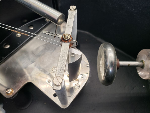
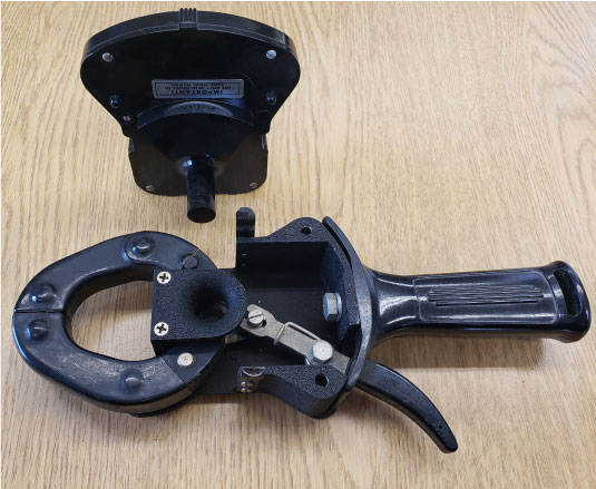
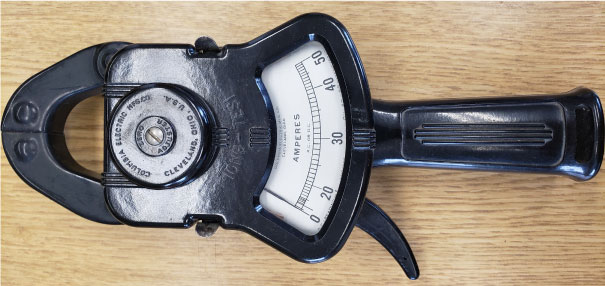
Elevated field strengths were also a useful engineering consideration when creating meter movements designed to measure AC current. The instrument below is a clamp-on current meter. It is called a Tong-Test, Model AX made by the Columbia Electric Manufacturing Company. This product was often sold with multiple sets of instrument heads, each with a specific current range that were connected to the base unit depending on the measurement range that was required.
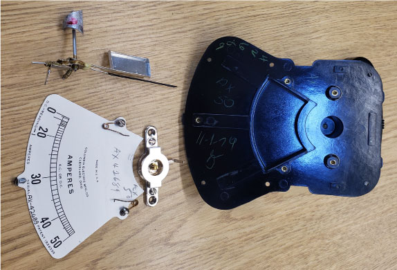
By breaking down the meter movement, we can see that under the scale it uses a damping vane to stabilize the pointer when a measurement is being made. Notice that the meter movement itself also has a small, curved triangular vane that occupies the space between the upper and lower pivot and jewel assemblies of the movement. This vane is lowered into the “throat” of the electromagnetic field created by the current transformer on the clamp-on assembly when the meter is connected around a current carrying conductor. The meter is calibrated by bending the small triangular vane in such a way that the entire mechanism creates the best possible deflection for all points in the measurement range. The artistry of creating such movements is similar to that employed in custom muffler shops that auto enthusiasts go to when they want a particular pitch to the sound of their classic cars.
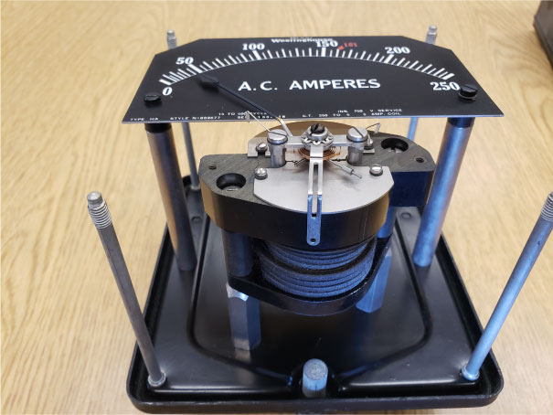
This principle is also the specific reason that most current transformers used in electrical power and distribution circuits are expressed as having ratios of something-to-five. That is because typical AC current meters that are used to measure the output of instrument current transformers utilize meter movements that have a five-amp field coil. AC current meters with five-amp field coils used in the electrical industry have been around for decades, as shown in the picture below. This Westinghouse Type HA AC current meter is like other instruments that have been around for more than one hundred years. When these instruments are connected in circuit, they exhibit an extremely low burden relative to other devices and loads connected in the same circuit.
In these last few examples, the observer effect mentioned earlier is of less significance to the testing scenario being observed. On the other end of the spectrum, things like destructive high-potential testing, or scanning-electron microscopy most certainly change the state of the test subject. It seems to be true that as time marches forward our observations are becoming less invasive in the energy spent making them and the ways in which they influence the test specimen.
It may be that devices, like the variety of deep-space telescopes that are now deployed, exhibit the least effect on the portions of the universe they observe as they allow us to witness events at times and places unimaginably far from our point of reference. Thinking of such things has always made me wonder, if some future type of observatory missed seeing something like an alien tree falling on a planet in some far-flung portion of the universe, would it have made a sound?
Dan Wiswell is a self-described Philosopher of Metrology. He is President/CEO of Cal-Tek Company, Inc. and Amblyonix Industrial Instrument Company. North Billerica, Massachusetts.