Summary
Inconsistencies plague the mains power line, and these problems negatively impact the performance quality of electronic (as well as virtually any precision) equipment. Cleaning the power results in one less potential source of error at the electronics test bench. In this white paper, we discuss commonly used solutions to these problems. We then introduce Mains Reconstruction Units (MRUs) and their revolutionary benefits to power lab equipment.
I. MAINS FREQUENCY, AMPLITUDE, AND WAVEFORM ISSUES
A Brief History of The Global Power Grid
Early AC frequencies used across the world ranged from 16.666 Hz to 133 Hz. Standardization took many decades to establish. In fact, in 1918, Great Britain alone used ten different frequencies, while many cities in Germany, Switzerland, and Italy used 40 Hz. By 1946, Europe had eventually standardized to 50Hz.
Meanwhile, North America standardized to 60 Hz in the 1920s, with some exceptions – much of California used 50 Hz until the late 1940s when it too standardized to 60 Hz. In Japan, standardization per se was never reached, even today. The western half of Japan used 60Hz, and the eastern half used 50 Hz – this is still the case today.
Of course, equipment that is designed for a particular region of the world will also be designed for the local mains voltage and frequency. In some cases, design tradeoffs are made which make this equipment unsuitable for operation in regions where either voltage or frequency are different. These tradeoffs could result in anywhere from performance shifts to disastrous consequences if equipment is powered on an inappropriate voltage or frequency. Power supply transformers and filters, motors or other electromechanical components operate differently at different mains frequencies. Most notably, synchronous motors will operate at the wrong speed when operated at the wrong mains frequency. In addition, transformers optimized for 60 Hz may begin to saturate (overload) when operated at 50 Hz.
Frequency Stability
In the United States, Time Error Correction (TEC) was established in the 1930s to regulate the frequency because of the hot new technology on the block – Henry Warren’s synchronous electric clock. TEC’s premise is simple: generators slow down when the power grid is loaded, and they speed up when the load decreases. The idea was to use timekeeping to regulate the speed of the generators, if only manually at first. In a fixed time frame (usually 24 hours), the overall number of cycles is thereby controlled to a constant level. Eventually, countries worldwide adopted this practice.
The modern power grid is an incredibly complex yet delicate electromechanical system; keeping frequency constant is a challenge everywhere globally. To further complicate matters, the organization that sets the direction and policy for the mains power grid in North America, NERC (North American Electric Reliability Corporation), is considering discontinuing TEC because of the expense and reliability issues incurred from maintaining TEC. If this were to happen, we will no longer be able to count on the mains frequency as a virtual timing standard. Frequency variations could increase substantially as well.
Frequency affects electronic equipment in significant ways. For example, a piezo fan’s performance relates directly to frequency. The fans will not function optimally at small variations of frequency of even plus or minus 0.1 Hz. Customers have demonstrated that this variation is indeed troublesome. As stated above, synchronous motors and transformers can develop problems as well. Even induction motors designed for 60 Hz can develop reliability issues when operated at 50 Hz. And equipment with power supplies designed for 60 Hz can experience increased heat and output ripple. These factors will impact reliability and affect circuits being powered by them.
Amplitude Stability
Over-voltage and under-voltage are well-known issues related to amplitude instability, but there are others. Slowly changing and transient amplitude changes are also problematic. Even short-term over-voltage (>140 V US) can cause damage or blow fuses, while under voltage can cause equipment to shut down or restart. Slow changes result in DC bias drift in instrumentation (as well as resulting stability and accuracy issues), and transient changes, such as distant lightning strikes, can be devastating to electronics. Keep in mind that even with multiple levels of protection (lightning rods, surge protection, isolation, and yet more isolation), it is impossible to prevent damage to electronic devices from a direct lightning strike.
It is possible to mitigate amplitude issues through electronic devices such as power conditioners and surge protectors. However, it’s important to note that mitigation is precisely that – none of these methods will prevent the consequences of surges, regulate frequency, or isolate. They also do not correct power factor issues (more on that topic later).
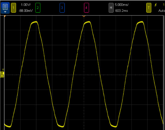
Waveform Purity
The power we’re getting in laboratories and businesses is distinctly sub-optimal. Figure A shows a waveform measured in an average US lab outlet with nothing turned on.
Power Factor
Power factor is a measure of how effectively and linearly an electronic device consumes power. In a purely resistive (i.e., linear) system, Ohm’s law sufficiently represents the relationship between voltage and current. A resistive load normally represents the ideal power factor of 1; this indicates a linear system, Figure B. However, with a nonlinear load, voltage and current can become out of phase with the current consumption waveform becoming severely distorted. As this distortion increases, the power factor decreases. As the value becomes a smaller fraction of 1, harmonic distortion increases, and presents itself as noise.
Figure C shows the mains voltage (yellow) and the mains current (green). Does it even resemble a sine wave? Most people don’t look beyond the purity of the voltage waveform – but it’s clear that a very high level of current distortion is happening here.

II. CLEANING UP THE PROBLEM
The Impact of Mains Power Line Issues On Electronic Equipment
How will you know how the mains power line is impacting the performance of your equipment? It largely depends on the equipment you’re powering, how sensitive it is, and how it processes power. However, the most frequently reported issues are differences in background noise. Some effects can even create electro-mechanically generated noise from the equipment’s transformers! A substantial shift in mains power line frequency can also shut down delicate instrumentation with a narrow operating frequency. Some measurement instrumentation can adapt to frequency or can be set to adapt. But how can you know for sure, for example, that a calibration performed in your 50 Hz laboratory will yield optimal results if the equipment is used in a 60 Hz laboratory somewhere else in the world?
Power Conditioners & Filters
Power conditioners smooth out small voltage fluctuations and eliminate harmonic content on the mains power. Their primary function is filtering, but many also protect against over-voltage, under-voltage, and power surges. Many provide the added benefit of additional outlets.
At the core of most surge protection, Figure D, is a voltage-suppression device called a MOV (metal oxide varistor), which helps keep electronic devices safe. These are fairly robust devices placed across the incoming mains voltage (of course, a fuse or fast-acting breaker needs to be inserted in front of these devices to prevent catastrophic damage).
And of course, these fuses or circuit breakers protect from other sources of catastrophic over-current such as internal device failures.
The challenge of using power conditioners lies in matching the device with the equipment being used. There is no guarantee that the power conditioner will make a significant difference, and the additional series impedance presented to the equipment’s power supply may very well impact power quality because of added series resistance.
DC Mitigation
DC on an AC power line is more common than many think. Any device plugged into the line can cause the problem if it presents the mains with an asymmetrical load, i.e., where one half of the sine wave is loaded more than the other half. Common laboratory heat guns and even incandescent lights can be culprits. In fact, anything that uses a half-wave rectifier for power supply generation or power reduction can introduce asymmetry in the mains power line.
The most common manifestation of DC offset is the power transformer in electronic equipment. Transformers under 100 watts are not generally problematic, but above that level the issue becomes quite noticeable. Equipment power transformers are highly sensitive to DC currents resulting from these offsets – even a few hundred milliamps can cause serious problems. This effect is quite audible and disturbing, and not healthy for the power supply.
There are several dedicated devices out there that help mitigate DC on the mains power line. These products put a capacitor in series with the input, clamped by high-current diodes to protect the capacitors. Unfortunately, while these devices might help, they don’t eliminate the problem—and introduce problems of their own.
Many power conditioners make a reasonable attempt at removing DC offsets. But there are practical limits to how much DC offset can be “removed” due to circuit component limitations, allowable internal power dissipation within these devices, and of course physical size and cost. Both toroidal and laminated core transformers are susceptible (contrary to many marketing claims). In extreme situations, DC offsets can cause blown fuses within the equipment due to power transformer saturation or flux drift.
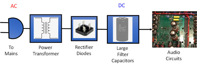
III. REVOLUTIONIZING POWER WITH THE MAINS RECONSTRUCTION UNIT
Mains Reconstruction Units (MRUs) start from scratch. They take the mains power, turn it into DC, and then back into AC (Figure E). Essentially, MRUs completely reconstruct the power line. The result is a pure sine wave (Figure F), the equivalent of having a precision power generator right in the laboratory.
MRUs eliminate waveform distortion, regulate voltage, and lower impedance – with minimal degradation to power factor. They provide full isolation from the mains and decrease current distortion reflected back to the mains power line.
The MRUs produced by KCC Scientific are presently available up to 1000 Watts power output. They work worldwide, with 115 V or 230 V, with 50 Hz or 60 Hz outputs. They offer integrated soft start, so they are easy on your system electronics.
CONCLUSION
As shown in the table below, MRUs are unparalleled in their ability to control frequency accuracy, regulate voltage, clean up the voltage waveform, soften current spikes, all the while protecting from brownouts, mains distortion, and transients.
| Effect | Filters | DC Mitigation | MRU |
| DC Offset | 0 | + | ++ |
| Frequency Stability | 0 | 0 | ++ |
| Amplitude Distortion | 0 | 0 | ++ |
| Output Impedance | – | – | + |
| RFI Noise | ++ | +(some) | ++ |
| Overvoltage Protection | + | +(some) | ++ |
| Brownout Protection | 0 | 0 | ++ |
| Isolation | 0 | 0 | + |
| Soft Start | 0 | 0 | + |
| PFC Correction | 0 | 0 | + |
| Total Benefit | ++ | +++ | ++++++++++++++ |
| Price | $200-500 | $200-300 | $179-2500 |
| Table 1. The benefits of MRUs compared to other solutions. | |||
At KCC Scientific, we solve countless power problems for customers worldwide, including medical-grade applications. Our products have helped our customers resolve hum problems, speed problems, and problems with the wrong local frequency or voltage – with resounding performance advantages–economically. We have made it possible to use manufacturing equipment designed for 50 Hz in a factory with only 60 Hz mains power. We have corrected issues with unreliable mains frequency, providing pure, isolated power so that instrumentation could be used over extended periods to map small changes or drifts.
About the Author
Ken Reindel, President of KCCScientific LLC, has worked in the test and measurement industry for 40 years. Ken is a master at product ideation and development in numerous high-tech electronic, electro-mechanical and electro-optic fields. His efforts include producing many successful, manufacturable products, which serve critical customer applications. His efforts have produced several patents and R&D awards. He has a degree in electrical engineering.
For more information visit www.KCCScientific.com